Bottom Toolbar
The Bottom Toolbar is the main interaction area of the 3D Viewer. It provides quick access to the most important tools for selecting objects, navigating the scene, adjusting the camera, changing visualization modes, and performing measurements directly in 3D.
Using the Bottom Toolbar, users can:
- Select elements in different ways
- Move and inspect the scene from different perspectives
- Switch between camera projection modes
- Change how geometry is rendered
- Measure distances, angles, areas, and clearances directly in the 3D Viewer
Selection Tool
The selection tools define how objects or scene elements are selected in the 3D Viewer. These tools are especially useful when working with complex setups or when multiple elements need to be inspected together.
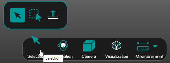
Available selection modes
- Default Selection – Allows users to select objects one by one. This mode is best suited for precise inspection or when the focus is on a single element.
- Area Selection Mode – Allows users to draw a selection box and select multiple objects at once. This is useful when several elements need to be reviewed or inspected together.
- Ray Drill Select – Allows users to select objects along a virtual ray projected from the camera through the cursor position. Instead of selecting only the first visible object, this mode can identify elements along the line of sight.
💡 Tip: Use area selection when you want to apply changes to multiple elements quickly.
Operator insights
- Use Default Selection for precise selection of individual objects.
- Use Area Selection to work faster with grouped or multiple elements.
- Use Ray Drill Selection when objects overlap and a deeper selection method is needed.
Navigation Modes
The 3D Viewer lets you explore your machining setup with precision, giving you multiple ways to navigate through the scene depending on your needs.
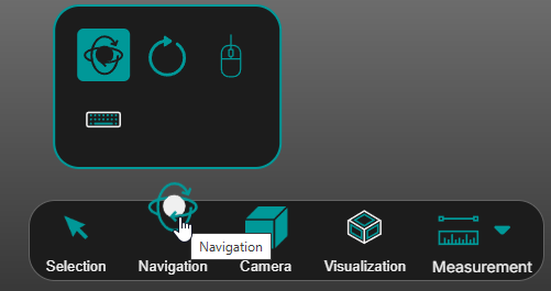
Click and drag to move the entire scene freely in any direction. This mode is perfect for quick adjustments and viewing different areas without changing orientation.
| Control | Action |
|---|---|
| Left mouse button + drag | Rotate the view |
| Mouse wheel | Zoom toward the cursor |
| Mouse wheel + drag | Pan the scene |
| Right mouse button + drag | Dolly zoom |
Controls details
- Left mouse button + drag: Rotate the view. When you left-click in the scene, a black dot appears at the selected location. This dot represents the pivot point around which the camera rotates.
- Mouse scroll: Zoom in or out toward the cursor. Scrolling the mouse wheel zooms the scene toward the cursor position in the 3D View (pivot point).
- Mouse scroll + click + drag: Pan the scene. The pivot point is where the mouse cursor position is in the 3D View.
- Right mouse button + drag: Dolly zoom. The pivot point is fixed at the center of the 3D View.
💡 Tip: The pivot point is defined by the cursor position. Knowing the pivot point for each control helps you navigate precisely and inspect your setup more efficiently.
Rotate the view around a fixed center point on the Z-axis. This is ideal for inspecting an object from all angles.
💡 Tip: The Turntable is great for rotating around the part.
Provides a first-person perspective, similar to walking through the setup. This immersive mode is useful for detailed inspection of complex or large arrangements.
💡 Tip: Mouse Walk gives a more immersive feel.
Provides a first-person perspective, similar to walking through the setup. This immersive mode is useful for detailed inspection of complex or large arrangements.
Operator insights
- Use Navigate for general scene inspection and quick orientation changes.
- Use Turntable when a stable rotation around the setup is preferred.
- Use Mouse Walk or Keyboard Walk when inspecting larger scenes in more detail.
Camera Settings
The 3D Viewer gives you control over how the scene is rendered, so you can adapt the view to your task and improve spatial understanding.
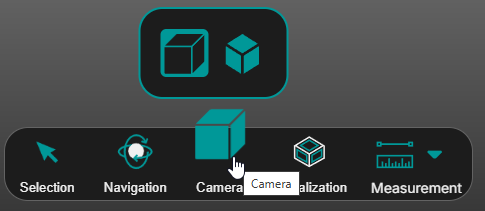
Perspective View Adds depth and realism to the scene, making it easier to understand spatial relationships.
Orthographic View Maintains true scale and proportions, which is essential for accurate measurements and alignment checks.
💡 Tip: Switch to Orthographic View when performing dimension checks or aligning elements precisely.
Operator insights
- Use Perspective View for general spatial understanding.
- Use Orthographic View when accurate visual comparison and alignment are more important than depth impression.
Visualization Settings
The 3D Viewer allows you to control how elements are displayed, giving you flexibility to focus on what matters most.
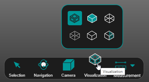
Available Rendering Modes

Shading – Displays only shaded faces, without edge lines, for a clean and minimal look.

Tessellation edges – Shows only the tessellation edges, useful for analyzing mesh structure.

X-Ray – Selected items remain fully visible, while unselected items become transparent, helping you see through overlapping components.

Gooch – Applies mid-tone shading so edges and contours remain visually distinct without harsh highlights.

Toon – Uses discrete shading levels for a stylized, cartoon-like appearance that emphasizes shape and silhouette.

Shading with edges – Renders faces and outlines, offering a clear, detailed view of geometry.
💡 Tip: Use Rendering Modes to reduce clutter and focus on specific elements during inspection or editing.
Operator insights
- Use rendering modes to reduce clutter and improve focus during visual inspection.
- Use X-Ray when hidden geometry or overlapping objects need to be reviewed.
- Use Shading with edges when geometric definition needs to remain clearly visible.
Measurement Tools
The 3D Viewer provides built-in measurement tools that let you check critical dimensions directly inside your machining scene. No need to switch applications or leave the workspace - you can quickly validate distances, clearances, and alignment.
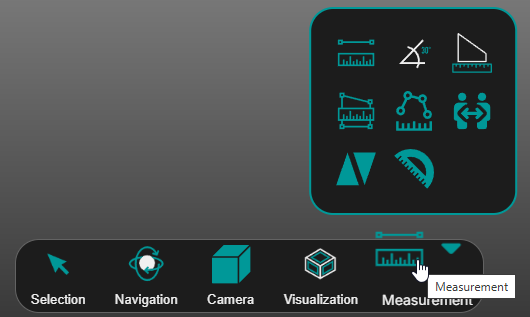
What you can do with the Measurement Tool
Point-to-Point Distance

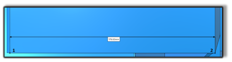
Point-to-Point Distance – Measures the distance between two points.
How to use
- Click to select the first point.
- Click to select the second point.
Line-to-Line Angle

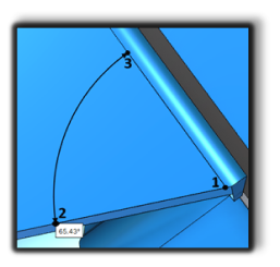
Line-to-Line Angle – Measures the angle between two lines (0-180 deg).
How to use
- Select the intersection (common point) of the lines.
- Click the first line.
- Click the second line.
💡 Tip: The angle between the lines is displayed after the second point is placed.
Edge Length

Edge Length – Measures the length of edges. For circles, it measures the radius.
How to use
- Click the edge that you need to measure.
Polygon Area

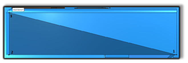
Polygon Area – Measures the area of a user-defined polygon.
How to use
- Click to add points, then double-click the last point to complete the polygon.
Polyline Distance

Polyline Distance – Measures the total length of a polyline.
How to use
- Click to add points.
- Double-click to finish an open polyline, or click the first point again to close the loop.
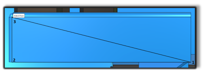
Body-to-Body Distance

Body-to-Body Distance – Measures the minimum distance between two bodies.
How to use
- Hover to highlight a body.
- Click to select it, then select a second body.
- Move the mouse to position the measurement label and click to finalize.
Face-to-Face Distance

Face-to-Face Distance – Measures the minimum distance between two faces.
How to use
- Hover to highlight a face.
- Click to select it, then select a second face.
- Move the mouse to position the measurement label and click to finalize.
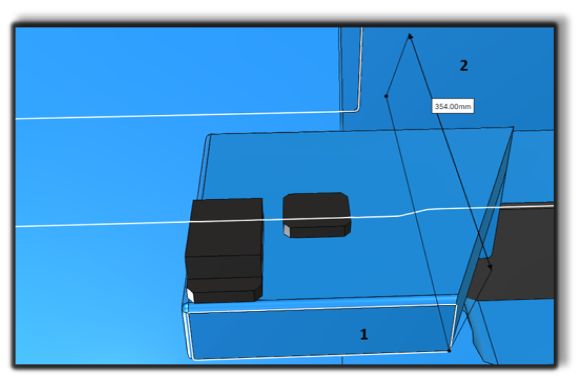
Face-to-Face Angle

Face-to-Face Angle – Measures the angle between two faces.
How to use
- Hover to highlight a face.
- Click to select it, then select a second face.
- Move the mouse to position the measurement label and click to finalize.
Operator insights
- Use measurement tools to confirm dimensions and clearances directly in the 3D scene.
- Use Orthographic View when performing precise geometric checks.
- Vertex snapping is enabled by default for measurement tools. To disable snapping temporarily, hold Alt before each selection.