Visibility Panel
Purpose
The Visibility Panel allows users to control which elements of the loaded setup are visible in the 3D Viewer. This supports visual inspection and analysis by reducing clutter in complex scenes and allowing users to focus on the elements relevant to the current task.
The panel is available from the right-side panel of the Shopfloor Assistant interface.
By showing or hiding resources, bases, or individual joints and axes, users can better understand spatial relationships, accessibility, and potential problem areas without modifying the program itself. Visibility changes are applied instantly and affect only the visualization, not the program data.
This functionality is intended for scene inspection and visual clarity, not for editing or teaching operations.
Typical use cases include:
- reducing visual noise in complex scenes
- isolating specific resources or joints
- focusing on collision-prone or hard-to-reach areas
- improving inspection clarity before validation
System Behavior
When visibility is changed in the Visibility Panel, the scene updates immediately in the 3D Viewer.
The viewer provides real-time visual feedback, allowing the operator to observe:
- spatial relationships between visible components
- accessibility of critical geometry
- fixture and resource context while isolating elements
- potential problem areas without changing program data
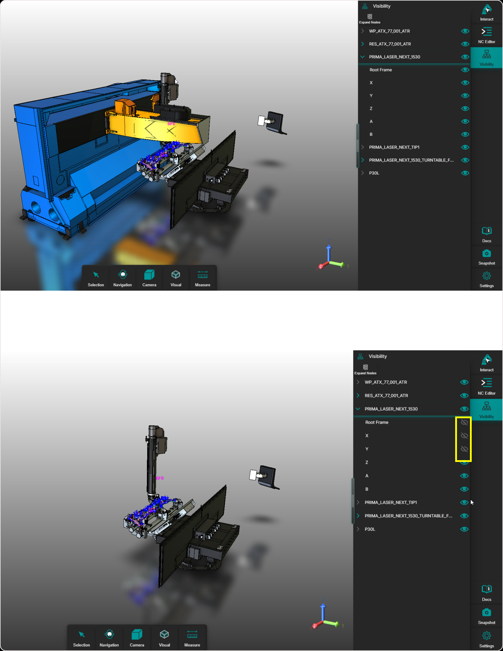
Each element in the model tree has a visibility icon:
- eye visible: geometry is shown in the 3D Viewer
- eye crossed: geometry is hidden
Visibility controls support both levels:
- toggling a parent node affects all child elements
- child elements can be controlled independently
Procedure
Step 1 — Open the Visibility Panel
Open the Visibility Panel using the visibility button located on the right-side panel of the Shopfloor Assistant interface.
Step 2 — Explore the Model Tree
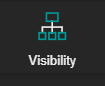
The Visibility Panel displays a hierarchical Model Tree representing the loaded setup. Depending on the project, the tree may include:
- workpiece
- resources (machine, robot, fixtures, tables, and related items)
- base geometries
- joints or axes
Nodes with child elements can be expanded or collapsed.
Step 3 — Toggle Visibility
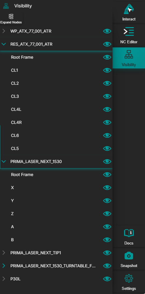
Clicking a node highlights and displays the corresponding resource, or part of it, in the 3D Viewer. This helps the user quickly identify the selected element in the scene.
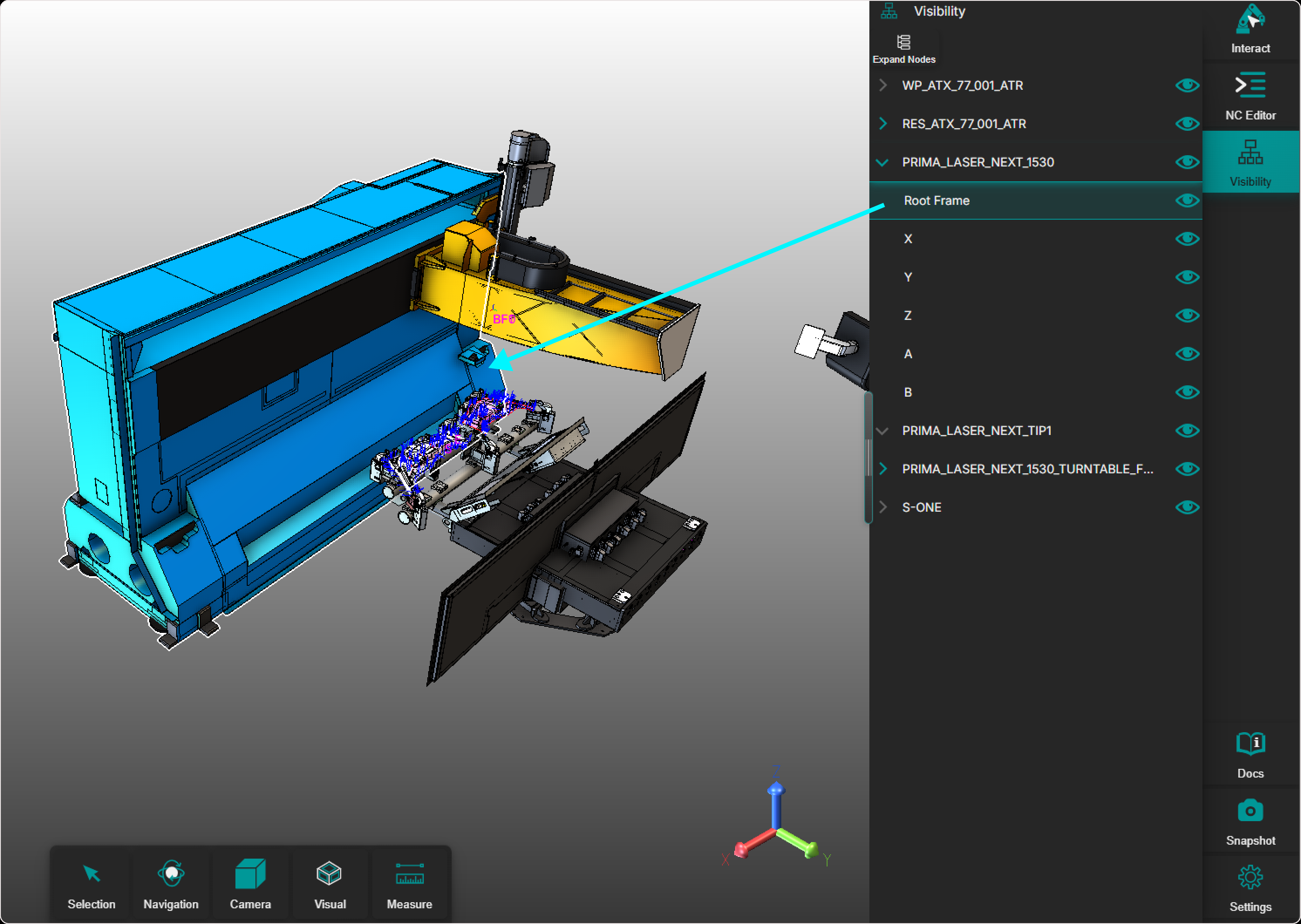
Each element in the tree has a visibility icon (eye):
- Eye visible → geometry is shown in the 3D Viewer

- Eye crossed → geometry is hidden

Clicking the visibility icon toggles geometry display for the selected node while preserving program data.
Step 4 — Focus on Relevant Geometry
Use visibility control to:
- hide surrounding or irrelevant geometry
- isolate specific resources or joints
- improve clarity during inspection, teaching, or validation
- navigate complex setups more efficiently
Operator insights
- Use the Visibility Panel to reduce visual noise in complex 3D scenes.
- Visibility control affects only visualization, not program data.
- Hide irrelevant resources when inspecting reachability, clearance, or collisions.
- Combine visibility control with navigation, rendering modes, and measurement tools for detailed analysis.
- Showing or hiding geometry does not change the result of editing or teaching workflows.