Color settings

In this command the Color settings of the different objects or activities can be defined. With the first installation of FASTSUITEEdition 2 all color settings will have a system default value that is stored in a user specific settings file.
The command opens a window with various containers with objects or interactions for which the color can be modified.
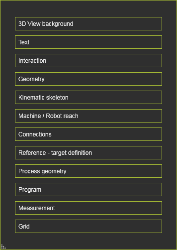
Color settings
| Category | Setting | Preview |
|---|---|---|
| 3D View background | Sets the global background color of the 3D View. Option to specify a single (solid) color or a top down gradient color scheme between two colors.  | 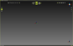 |
| Text | Sets the text color of the 3D Headup display and other text elements. | 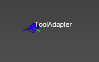 |
| Interaction | On mouse over: Sets the appearance of an object when hovering the mouse over that object. Two options are available to specify the final appearance. | 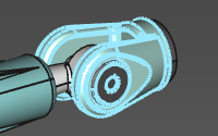 |
| Interaction | On selection: Sets the appearance of an object when that object has been selected. Two options are available to specify the final appearance. | 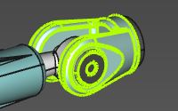 |
| Interaction | On active object: Sets the appearance of the active object. Two options are available to specify the final appearance. | 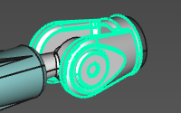 |
| Geometry | Display: Sets the color of additional objects, such as a point at the mesh vertex, or a circle center. | 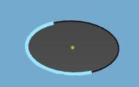 |
| Geometry | Body edge: Sets the color of the edges of the exact geometrical bodies. | 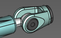 |
| Geometry | Wireframe: Sets the color of the wire-frame based geometry. | 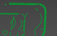 |
| Kinematic skeleton | Driven and synchronous joints: Sets the color of the main kinematic chain. | 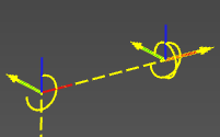 |
| Kinematic skeleton | Asynchronous joints: Sets the color of the asynchronous external kinematic axes. | |
| Kinematic skeleton | Undriven auxiliary joints: Sets the color of the undriven, auxiliary kinematic chain. | 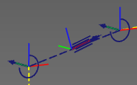 |
| Machine / Robot reach | Sets the color of the geometry that describes the reach of a resource, mostly a robot. | 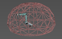 |
| Connections | Sets the color of the adapter connections. | 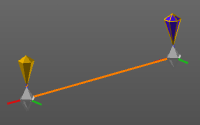 |
| Reference - target definition | Reference: Sets the color of the reference object when relations are being created, for example at calibration. | 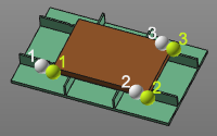 |
| Reference - target definition | Target: Sets the color of the target object when relations are being created, for example at calibration. | |
| Process geometry | Programmed process geometry: Sets the color of the process geometry that has been used for OLP programming. | 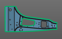 |
| Process geometry | Unprogrammed process geometry: Sets the color of the process geometry that has not been used for any OLP program yet. | 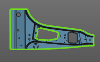 |
| Process geometry | Surface outer boundary: Sets the color of the selected boundary of surface process geometry. | 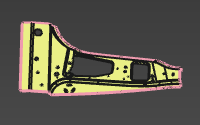 |
| Program | Operation: Sets the color of the operations that are applied on the process geometries and their order. | 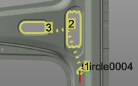 |
| Program | In-process path: Sets the color of the in-process section of the operation. | 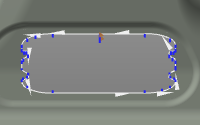 |
| Program | Regular shape in-process path: Sets the color of the in-process section of the operation of a regular shape operation. | 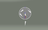 |
| Program | Auxiliary path: Sets the color of the auxiliary section of the toolpath. | 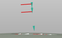 |
| Program | Approach / retract path: Sets the color of the approach and retract sections of the operation. | 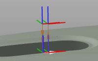 |
| Program | Operation link path: Sets the color of the operation link section of the toolpath, i.e. the motion between two operations. | 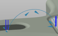 |
| Measurement | Sets the color of the measurement result objects. | 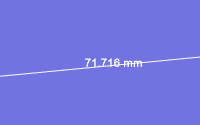 |
| Grid | Sets the color of the grid that is used for layout setup. | 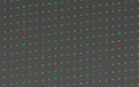 |
Options of On mouse over, On selection and On active object
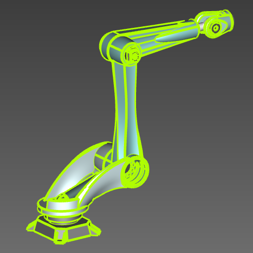
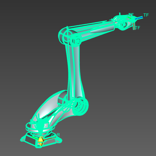
In the On mouse over, On selection and On active object color settings there are two options that define the final display of that interaction.
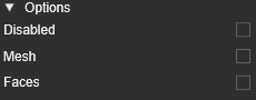
These interactions have a default, non-editable color. This color is applied on the edges of the geometry and several other objects, such as joints and frames.
| On mouse over | On selection | On active object |
|---|---|---|
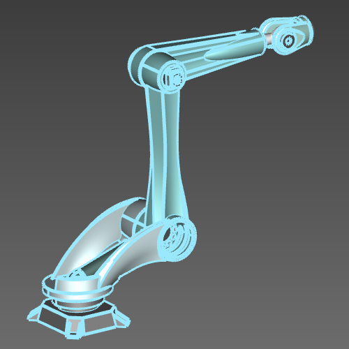 |  |  |
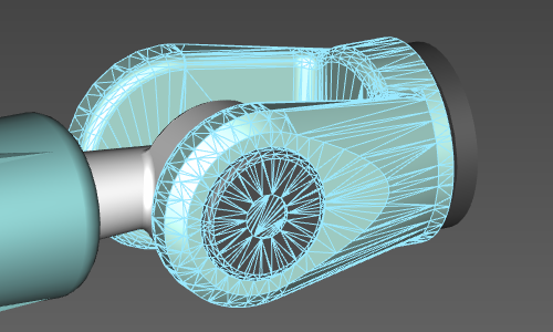
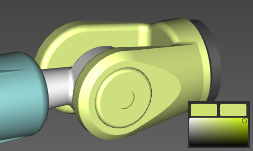
With the additional two options, the appearance can be enhanced especially for the highlight of geometry. The Mesh option stops the edge-highlight on the geometry and will highlight the tessellation of that geometry. The Faces option will display the faces of the geometry with the defined color.
| Mesh | Faces |
|---|---|
 |  |
The option Disabled is only available in the On mouse over color definition. Obviously, it disables any highlight coloring when the mouse hovers over an object.
Color value
The color value is based upon the RGB color system and can be set in a small interactive area.
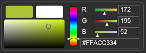
The interactive area includes color picking area on the left, a vertical slider for the color range and three horizontal sliders to modify the individual Red, Green and Blue values. The corresponding decimal values are displayed and also editable in the fields on the right side of the interactive area. The color HEX value is also displayed and editable in the filed below the individual RGB settings.